by Matt | Jun 23, 2012 | Projects
New code here v2.4 On v2, I didn’t assign all the directional wires PWM pins, and it caused me to use the purple wire as speed which was unnecessary. In v2.1 the speed and direction come from the direction wires. Also, I learned from this link the Bescor goes to ground at limit which means it will stop moving overtime when it goes in two directions. By using 1.5k resistors on each end of the four wires, the Bescor doesn’t reach the ground limit. White = up Blue = down Yellow = left Green = right White = pin 10 Blue = pin 9 Yellow = pin 11 Green = pin 3 The Bescor had a lot of electrical noise, so I changed the PWM frequency using this code. /* * * This program controls the Bescor MP-101 Pan/Tilt system using the Wii Nunchuck * * Copyright (c) 2012 Matt Alford, http://www.protechy.com * Date: June 23, 2012 * * Nunchuck Library created by Gabriel Bianconi, http://www.gabrielbianconi.com/ * */ #include "Wire.h" #include "ArduinoNunchuk.h" // The library used by the Nunchuck #define left 11 //Pin 12 controls left pan #define right 3 //Pin 10 controls right pan #define up 10 //Pin 9 controls up tilt #define down 9 //Pin 8 controls down tilt ArduinoNunchuk nunchuk = ArduinoNunchuk(); int varx = 0; // The x-axis variable to store the value coming from the Nunchuck int vary = 0; // The y-axis variable to store the value coming from the Nunchuck int absx = 0; // The x-axis variable used to store the absolute value. int absy = 0; // The y-axis...
by Matt | Jun 1, 2012 | Projects
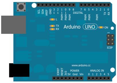
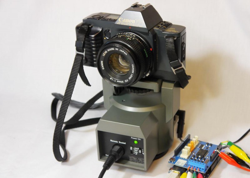
This is a followup of a better way to control the Bescor using the Arduino UNO from this tutorial (Update: Working on a new setup and hopefully have the code up soon.) Here’s a breakdown of how the original controller works . White = up Blue = down Yellow = left Green = right Black = Ground Red = 5v Purple = Speed When a button is pressed, an electrical current passes through one of the directional wires to the Bescor. The red wire is 5v and sends the current through the slider that changes the voltage and returns to the Bescor through the purple wire. I’m still experimenting, but here’s how I connected the wires to the Arduino using the original Bescor controller White = pin 8 Blue = pin 9 Yellow = pin 10 Green = pin 12 Purple = pin 3 Without looking inside the Bescor, I didn’t know if this is the best setup. I tried connecting the direction wires and ground to control the speed, but it didn’t work. The solution was to use the purple wire as my speed control and change the voltage like on the Bescor controller slider using PWM. The direction can be controlled by setting the digital pins HIGH “on” or LOW “off”. Here’s the code: /* * * This program controls the Bescor MP-101 Pan/Tilt system using the Wii Nunchuck * * Copyright (c) 2012 Matt Alford, http://www.protechy.com * Date: April 19, 2012 * * Nunchuck Library created by Gabriel Bianconi, http://www.gabrielbianconi.com/ * */ #include #include "ArduinoNunchuk.h" // The library used by the Nunchuck #define left...
by Matt | May 9, 2012 | Projects
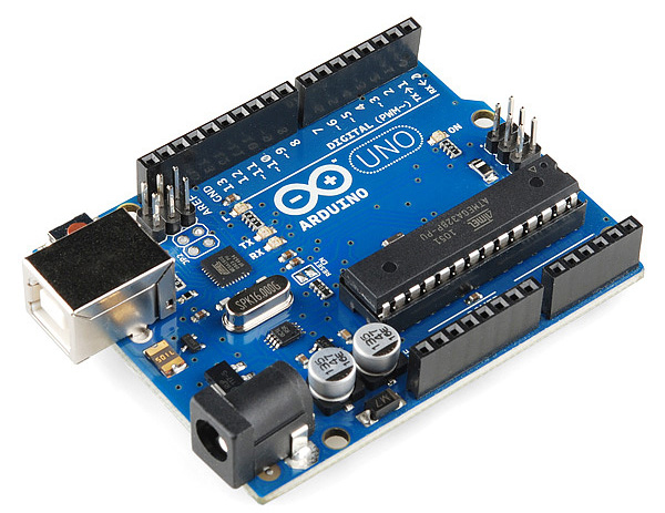
In this tutorial, I’ll show you how to install the Arduino Software and drivers on a Window 7 64-bit computer. Step 1: Download and Installation Download the Arduino Software here Download and extract the zip file in any location. I put mine on the desktop. Open the arduino-1.0 folder. This folder contains all the files and drivers needed to upload programs “sketches” to the Arduino. Step 2: Driver Installation I’ll show you how to manually install the Arduino Uno drivers on a Windows 7 64-bit computer. Generally, the older versions of the Arduino can be installed on there own. Click on start and go to control panel and click on System and Security. Click on System Click on Device Manager Let’s plug in the Arduino using the usb cable and see the Arduino as a unknown device. Right click on the Unknown device and click properties and select the Driver tab and click Update Driver. Click on Browse my computer for driver software Browse to the Arduino folder we unzipped and select the drivers folder Click Next and a security window may popup, but we want to install the driver. The Arduino should be listed under Ports in device manager after we installed the driver. Step 3: Running and Testing the Arduino Software Back in the Arduino folder, click on the Arduino blue icon. Let’s upload a example sketch to the Arduino. Click on File, Examples, 1.Basics and click Blink. While the Arduino is plugged in to the computer via usb, make sure the Arduino Uno board is selected under Tools – Board. Finally, upload...
by Matt | May 1, 2012 | Projects
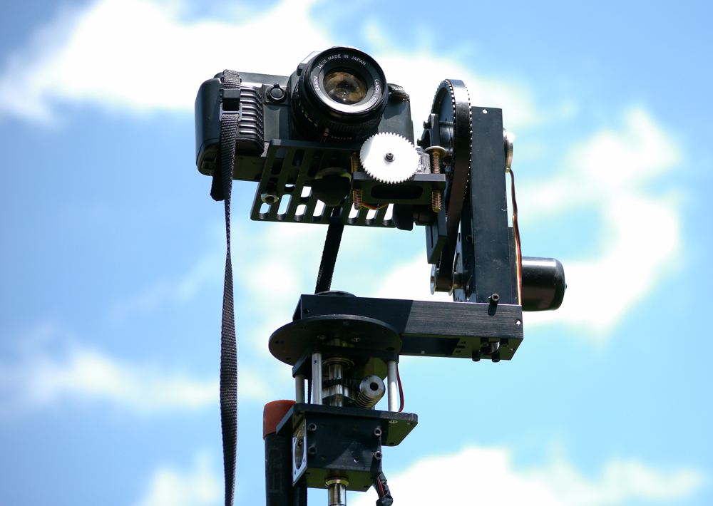
[av_video src=’http://vimeo.com/41374127′ format=’16-9′ width=’16’ height=’9′] I started this project a few months ago to record video at a distance of 18 meters. Most pan and tilt systems I tried were not suited for slower and smoother speeds, but with the modified PT785-S System from ServoCity, I was able to get smoother control. I used ServoCity’s worm drive to get slower motion and more toque. Also, sometimes I needed to mount the camera up high. This is the light stand I used. The stand is reinforced with two galvanized steel pipes. The controller took the longest to build. This is a early picture of the inside showing the motor driver and Arduino. I have a Ethernet cable running to the motors and servo from the Arduino...
by Matt | Apr 18, 2012 | Projects
New Tutorial Here – July 4, 2013 Update: Thanks to Bill Porter, there is a better way to connect the Bescor to the Arduino instead of using the Motor Shield. I’ll try to get a working prototype up this week. Here’s the link [av_video src=’http://vimeo.com/40569055′ format=’16-9′ width=’16’ height=’9′] The Bescor MP-101 pan and tilt is a great cost effective solution for video and photo setups, but it has several limitations. First off, the controller only allows movement on one axis at a time. Also, the speed slider is difficult to use while panning. I searched for a better remote, but couldn’t find one at a reasonable price, so after trying a few experiments, I found using the Nunchuck, the Arduino, and the motor shield together, I could make a great controller. Step 1: Strip the MIDI Wires I’ll be using a five pin MIDI cable like this one. It’s also possible to use the original cable. (Note: The wire colors from other cables might be different from the original cable.) Step 2: Strip the Nunchuck Extension Wires To connect the Wii Nunchuck controller, I used this extension. Yellow – Ground Black – Clock Red – Data Brown – Power These wires will connect to the Arduino pins and later I’ll show in the code the pin assignments. If you use a different extension, the wire colors might be in a different order. Here is the Nunchuck pinout. Step 3: Connect the Nunchuck Wires to the Arduino Motor Shield The wires are connected as followed on the motor shield: Yellow –...