New Tutorial Here – July 4, 2013
Update: Thanks to Bill Porter, there is a better way to connect the Bescor to the Arduino instead of using the Motor Shield. I’ll try to get a working prototype up this week. Here’s the link
[av_video src=’http://vimeo.com/40569055′ format=’16-9′ width=’16’ height=’9′]
The Bescor MP-101 pan and tilt is a great cost effective solution for video and photo setups, but it has several limitations. First off, the controller only allows movement on one axis at a time. Also, the speed slider is difficult to use while panning.
I searched for a better remote, but couldn’t find one at a reasonable price, so after trying a few experiments, I found using the Nunchuck, the Arduino, and the motor shield together, I could make a great controller.
Step 1: Strip the MIDI Wires
I’ll be using a five pin MIDI cable like this one. It’s also possible to use the original cable. (Note: The wire colors from other cables might be different from the original cable.)
Step 2: Strip the Nunchuck Extension Wires
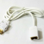
To connect the Wii Nunchuck controller, I used this extension.
Yellow – Ground
Black – Clock
Red – Data
Brown – Power
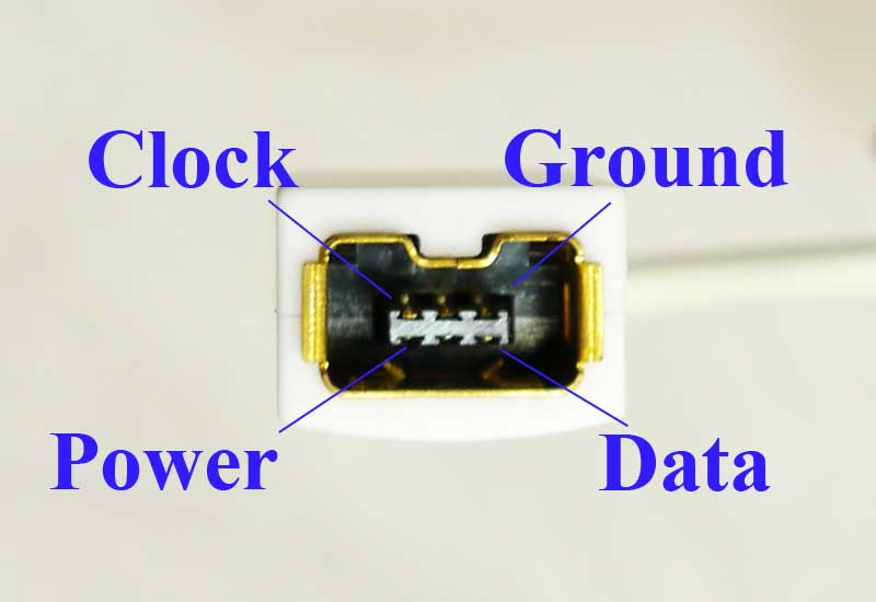
These wires will connect to the Arduino pins and later I’ll show in the code the pin assignments. If you use a different extension, the wire colors might be in a different order. Here is the Nunchuck pinout.
Step 3: Connect the Nunchuck Wires to the Arduino Motor Shield
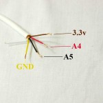
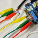
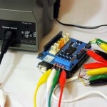
The wires are connected as followed on the motor shield:
Yellow – GND
Black – A5
Red – A4
Brown – 3.3v
Step 4: Connect the MIDI Wires to the Arduino Motor Shield
The wires are connected as followed:
Yellow– (-B)
Blue – (+B)
Purple – (-A)
Red – (+A)
Yellow/Blue – Tilt, Purple/Red – Pan
Step 5: Program the Arduino
In this step, the Arduino software and drivers need to be installed on the computer. If anyone’s interested in a in depth tutorial about using the Arduino software, please leave a comment. (Update: Here’s a link to installing the Arduino Software.)
Here’s a link to the library we’ll be using to get the Nunchuck working.
Each line of code below will be labeled and hopefully help you understand the process. If you have any questions, please contact me or leave a comment.
/*
* Arduino Pan/Tilt http://vimeo.com/40569055
*
* This program controls the Bescor MP-101 Pan/Tilt system using the Wii Nunchuck
*
* Copyright (c) 2012 Matt Alford, http://www.protechy.com
* Date: April 19, 2012
*
* Nunchuck Library created by Gabriel Bianconi, http://www.gabrielbianconi.com/
*
*/

#include "Wire.h"
#include "ArduinoNunchuk.h" // The library used by the Nunchuck

//Motor Pan left/right
#define motorB 13 // Pin 13 controls the direction of Motor B using the values 0 and 1
#define speedB 11 // Pin 11 controls the speed of Motor B using the values 0-255.

//Motor Tilt up/down
#define motorA 12 // Pin 12 controls the direction of Motor A using the values 0 and 1
#define speedA 3 // Pin 11 controls the speed of Motor A using the values 0-255

//The instance of the Nunchuck class
ArduinoNunchuk nunchuk = ArduinoNunchuk();

int varx = 0; // The x-axis variable to store the value coming from the Nunchuck
int vary = 0; // The y-axis variable to store the value coming from the Nunchuck
int absx = 0; // The x-axis variable used to store the absolute value.
int absy = 0; // The y-axis variable used to store the absolute value.

void setup()
{
Serial.begin(115200); // Opening the serial port
nunchuk.init(); //Initialize the Nunchuck code

//Sets up motor pin output
pinMode(motorA,OUTPUT);
pinMode(speedA,OUTPUT);
pinMode(motorB,OUTPUT);
pinMode(speedB,OUTPUT);
}

void loop()
{
nunchuk.update(); // The Nunchuck values update in the loop

// Read the values from the joystick and calculate the distance from center
// 130 is the distance from 0 on the joystick
varx = nunchuk.analogX - 130; // nunchuk.analogX is the value of the x-axis
vary = nunchuk.analogY - 130; // nunchuk.analogY is the value of the y-axis

// The values used for speed
absx = varx;
absx = abs(absx); // Convert the x-axis value to an absolute value
absy = vary;
absy = abs(absy);

// Run motor A based on the input from the joystick
if (varx >= 1)
{
digitalWrite(motorA, 1); // Direction of the tilt "up"
analogWrite(speedA, absx * 2); // Multiplied by 2 to increase the values 0-255
}

if (varx <= -1)
{
digitalWrite(motorA, 0); // Direction of the tilt "down"
analogWrite(speedA, absx * 2);
}

// Stop motor A when joystick is in the center
if (varx <=1 && varx >= -1)
{
analogWrite(speedA, 0);
}

// Run motor B based on the input from the joystick
if (vary >= 1)
{
digitalWrite(motorB, 1); // Direction of the pan "right"
analogWrite(speedB, absy * 2); // Multiplied by 2 to increase the values 0-255
}

if (vary <= -1)
{
digitalWrite(motorB, 0); // Direction of the pan "left"
analogWrite(speedB, absy * 2); //
}

// Stop motor B when joystick is in the center
if (vary <=1 && vary >= -1)
{
analogWrite(speedB, 0); // turn off if the joystick is in the center
}

// Print values for debugging to see what's going on
Serial.print("x-axis ");
Serial.print(varx);
Serial.print(", speed ");
Serial.println(absx * 2);
Serial.print("y-axis ");
Serial.print(vary);
Serial.print(", speed ");
Serial.println(absy * 2);
}

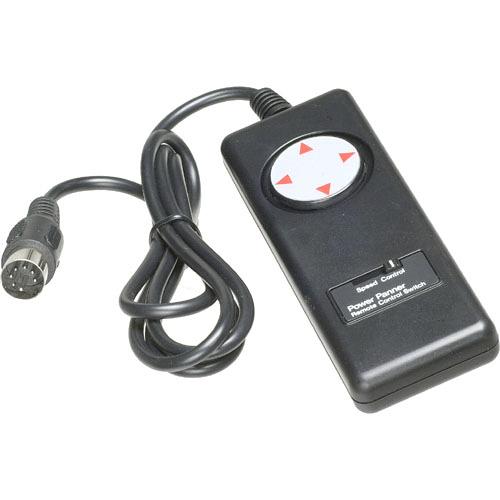 controller
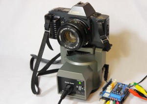
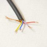
 Here
Here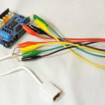
Hi Matt,
Very smart looking website.
I’m looking forward to trying this project. I have a Panasonic HMC-150 video camera that has outputs for Focus/iris and Zoom/Rec controls that I would also like to control remotely.
Thanks for sharing your work.
Cheers,
Stewart
The HMC-150 is a nice camera, and I’d love to hear how well your project goes. Also, I like your editing of The Atlanta Opera videos.
That’s cool and I want to buy one or more!
How about launch a Kickstarter program?
It could be a fun adventure to start a Kickstarter project and build a control that could use the Bescor MP-101 for joystick control and possibly for automated time lapses.
Matt, I’m still having trouble reconciling your MIDI wire color hookup to this http://etc.rheumatictangle.net/2011/04/17/bescor-mp-101-hack/ interpretation of the wire outputs.
Also, Am I correct that the tilt is yellow/blue not white/blue in step 4.
Cheers,
Stewart
On his flickr page he wrote the colors: Green = right, Yellow = left, Blue = down, and White = up. It might connect to the Arduino Motor Shield like this: Green = (-B), Yellow = (+B), Blue = (-A), and White = (+A). Tell me if it works and I’ll include the color outline of the original cable in this tutorial. Also, thank you for catching the correct colors: yellow/blue.
Matt,
Someone pointed me to your site wondering why you used a motor shield, and I’m a bit unsure why you chose to as well. Here are my observations:
It seems the original controller simply tied each direction button to GND (through a resistor). To mimic that, directly attaching each direction wire to an IO pin is suitable.
A motor shield is a H-bridge driver; meaning it expects to be directly connected to motor coils. To move one direction, it attaches one wire of the coil to positive (+) and the other to negative (-). To move the other direction it reverses which wire gets + and which gets -.
I think it happens to work as it is because one wires ends up getting pulled to negative (-) like the original controller use to do. However this must mean there is a common negative connection between the Arduino and the camera mount. He used a MIDI cable that does not bring out the negative pin on the controller connector, so I don’t see how that common connection is made. It may be that the H-bridge tying the other direction pin to positive (+) is actually creating a common positive (+) connection between the controller and the mount, and the forced voltage differential created by the H-bridge brings the other controller pin close enough to it’s own negative (-) connection that the mount moves.
So this is working, but it’s a very convoluted way to go about it.
Am I missing something to why you are running these low power control wires through a large motor shield?
Your right about the H-bridge, we can control it without the Motor Shield. I’m trying put together some new code and hopefully get it up by the end of the week. I haven’t tried it, but by connecting the four wires and the ground to the Arduino we can essentially control it like a LED light.
Ok, good to know. From just pictures I figured I could have missed something, so I wanted to be sure. Thanks.
Would you be willing to make one of these and sell it?
You might also be interested in this product that uses the Bescor. http://www.thegadgetworks.com
It is different in that you use a phone app to define the task (pano, timelapse, HDR, etc) and identify the characteristics of your camera and lens (focal length, aspect ratio, crop factor) and various timing information, Once you make those settings, you save them in a file on your phone that you can reload at any time. The phone app then generates a program that it transmits to the head via Bluetooth, and the embedded microprocessor interprets the program to operate the motors and fire the shutter. It can rotate 360 degrees continuously.
I am partial to this solution because I designed it but the Arduino solution is cool too.
Very neat, the Bescor has a lot of potential. I have seen something similar on http://www.bodenmedia.com/, but it has been on preorder for over a year now.
Hi.
what kind of motors you have in that moving head? they have an internal power supply?
what i need to modify in this code, if i use the motors shield`s power supply for 2 dc motors?
please help!
I’m not sure the exact dc motors that are in the Bescor MP-101, but yes, it has a internal power supply. This post is a old method I used to control the Bescor. I originally used the motor shield, but it was unnecessary because you could control it with pwm.
I recently acquired a Bescor MP-101 and upon looking for ways to improve on it, found this site. I’ve adjusted it to allow it to rotate 360 degrees and began tinkering on a way to make it wireless. I grabbed a cheap ole rc car I had laying around and tapped into the controls. I can move the head left and right, but there’s an issue with up and down. I can connect either the down or the up wires and it’ll work for one of those movements. But with both up and down connected, it won’t move up or down at all. Left and right always work. During your course of toying around with the head, did you notice anything which would possibly prevent up or down movement? Thanks
Hi,Jason, good morning
Can you explain me how to connect the wires to the receiver?
I have the bescor and I’m trying to use it in a wireless mode with a RC radio
Thanks Eugenio
Eugenio,
Did you ever find a solution for this? I am trying to do the same thing and I have to believe it is a simple task of correctly wiring the 7pin DIN connector to the RC Receiver plugs. I already use this adapter to control the zoom/record on my Sony Camera and it works nice:
http://www.rcshutter.com/index.php?route=product/product&filter_name=Zoom&product_id=82
But now I want to control the Pan/Tilt on the Bescor MP-101 with my RC Radio (Flysky 8 channel).
This will be a very inexpensive solution for remote control PTZ camera. We have them in the endzone for our highschool football games.
Tim
Hi Tim,
Did you ever get an RC controller to control the pan tilt head. Would be interested to know how you manage to get it working. The information you have provided for the adapter to control a Sony camera it great.
I am using for an end zone camera to record rugby games.
Appreciate any information I can get. Thanks
I ran into a similar problem when I was trying to figure out which wires to use, but it might not be the issue.
This is the wire color scheme from the original controller. It could be different on other controllers.
White: Power
Red: Ground
Black: Up
Blue: Down
Yellow: Left
Green: Right
Hi Matt, good morning.
Can you send an email to Jason just to inform him I’d like to contact him?
Thank you
Eugenio Lupoli
Sorry, I won’t be able to. I see you want to connect a receiver to the Bescor. You can connect it to the Arduino and control the Bescor. Here’s a tutorial on how to connect it to the Arduino. https://www.sparkfun.com/tutorials/348
Hi! I would *love* to get my hands on a wireless R/C-type solution to control both my Bescor MP-101 head *and* send LANC data to a camcorder sitting on the head.
Anyone have a solution for this?
Hmm, I could have sworn when I was tracing all the wires that black was ground, red was one end of the speed control (purple the other end) and white was up. If what you say is true, then that might be my answer. I’ll relocate some wires and see if that’s what the problem is. Thanks!
Sunnuva! That was it. The white and black had to be swapped. I had misread the circuit board and got them swapped by accident. Thanks again!
I will be interested in a kickstarter
Amazing Job,,,,
after i saw your Tutorial., i ordered every thing and fllowed you guide., it’s working real good., thanks to you., but i’m facing only one problem., when i use bluetooth Nunchuck controller, it’s like move then stop then move,,, every sec. do you have any idea why? Please can you help me., Thanks again
The data flow coming from the Bluetooth Nunchuck might be different from the way the Arduino library interprets it. I would try to using a different library. Here’s one that might work: https://github.com/GabrielBianconi/ArduinoNunchuk
For Bescor head, did you get one that is not modified? There is a seller on Amazon that modified it so that it turns 360. If I get the modified Bescor, would it still work with this instruction?
It will work. I have the modified and 180 degree version. Here’s the latest instructions: http://protechy.com/bescor-mp-101-hack-part-1/
Is it compatible with L293D Motor Drive Shield?
It would probably work, but I would recommend using the Arduino without the shield. http://protechy.com/bescor-mp-101-hack-part-1/
Thank’s. I’ve just ordered the Arduino on ebay and I had never experiences with it. I want to use this project in the church for making movie. The distance between bescor and nunchuck about 80 ft. Can I use cat5e cable instead of bescor cable or it will better to use wireless nunchuk?
I would try using the Cat5e cable.
Does this new controller and system allow the MP101 to pan slower? I have the MP101 and the remote that comes with the unit is fine its just too fast for my taste. Does this allow for slower panning? Thanks for your time 🙂
It pans a little slower with the Arduino. You can push it close to a stop, but it will stall.
Is there any possibility of precise absolute positioning of the head? For example I would need to rotate in one axis from 0° to 5°. I could do this by computing time needed for rotation for 5 degrees, but I am not sure if the speed of rotating is consistent (decreasing battery voltage, battery/adapter change). Is there any way to precise control the speed of rotating? The best way would be to have some feedback from the head with current position, but this is not available. Do you have any ideas??
You might be able to make it like a servo. http://dronecolony.com/2008/07/24/diy-servo-with-arduino-dc-motor-and-potentiometer/ I’m not sure it would work, but if there was a way to connect a potentiometer and a gear to turn while connected to the Bescor, you could control its position.
Can thee motor shield control the LANC on the video camera?
Thanks
The motor shield cannot directly control the LANC, but it does pass the Arduino’s inputs through the top and therefore the Arduino can control the LANC.